CYG400 Series · Water-Cooled High-Temperature
CYG409 Water-Cooled Dynamic Pressure Sensor: 450 °C / 2000 °C
The CYG409 is a water-cooled, high-frequency dynamic pressure sensor for extreme high-temperature service. Continuous operation reaches 450 °C, with transient peaks to 2,000 °C for 200 ms or 1,000 °C for 1,000 ms. Natural frequency runs 200 to 1,000 kHz across a 1 kPa to 100 MPa range, split between a low-range and a high-range model.
450 °C
Continuous
2000 °C
Transient / 200 ms
200–1000
kHz Natural Freq
1 kPa–100 MPa
Two Range Models
Family Position · Specifications · Jacket Design · Applications · Comparison · Ordering · Installation · Related · FAQ · Contact
Where the CYG409 Sits in the CYG400 Dynamic Pressure Family
The CYG400 piezoresistive dynamic pressure family covers ten models, grouped by mounting form: cased pressure-tap mount, free-field probe, underwater transmitter, and composite ground-stress probe. The CYG409 is the water-cooled cased variant at the top of the temperature ladder.
- For high-frequency dynamic measurement on a screw-in cased probe at standard temperature, see the CYG401 high-frequency dynamic pressure sensor (4 to 100 MPa, no water cooling).
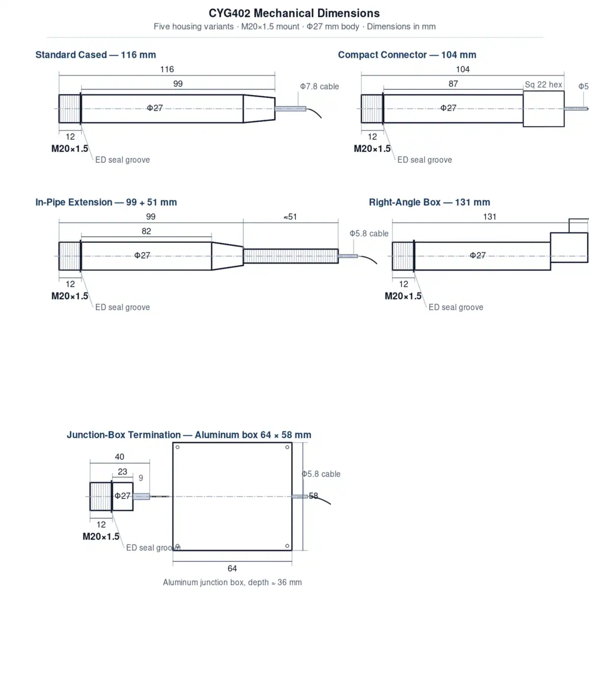
- For 180 °C continuous on a cased piezoresistive sensor, see the CYG402 high-temperature piezoresistive pressure sensor.
- For outdoor low-pressure blast wavefront measurement, see the CYG410 free-field pressure sensor.
The CYG409 fills the gap above the CYG402. A water-cooled jacket pushes continuous operation from 180 °C to 450 °C and lets the sensor survive transient peaks well beyond a thousand degrees, on the same piezoresistive sensing element that the rest of the family uses.
Full Specifications: Low-Range and High-Range Models
The CYG409 ships in two factory-paired variants that share the same water-cooled body but use different sensing diaphragms. The low-range model covers 1 kPa to 600 kPa for combustion and shock-tube work where peak pressure stays modest. The high-range model covers 1 MPa to 100 MPa for closed-bomb, gun-chamber, and explosive ordnance testing. Accuracy, non-linearity, and temperature coefficients are tighter on the low-range build because the diaphragm sees less mechanical strain per full-scale cycle.
Two tables follow. The first lists the sensor-only specification, which applies when the CYG409 head is used with a user-supplied bridge amplifier or DAQ front end. The second adds the matched CYG1409 in-line transmitter signal-conditioning module, which converts the millivolt bridge output into a 4-20 mA or 0-5 V signal for long-cable plant deployments.
Sensor-only specification (mV/V bridge output, no transmitter)
| Parameter | Low-range model | High-range model |
|---|---|---|
| Pressure range | 1 kPa to 600 kPa | 1 MPa to 100 MPa |
| Natural frequency | 200 kHz to 500 kHz | 500 kHz to 1,000 kHz |
| Rise time | µs class | µs class |
| Combined accuracy | ±0.25 % FS | ±0.5 % FS |
| Non-linearity | ±0.15 % FS | ±0.25 % FS |
| Zero-point time drift | 0.1 mV / 8 h | 0.1 mV / 8 h |
| Zero temperature coefficient | ±0.02 % FS / °C | ±0.03 % FS / °C |
| Sensitivity temperature coefficient | ±0.02 % FS / °C | ±0.03 % FS / °C |
| Compensated temperature range | 30 °C to 100 °C | 30 °C to 100 °C |
| Continuous operating temperature | 0 °C to 450 °C | 0 °C to 450 °C |
| Transient temperature limit (dual-mode) | 2,000 °C / 200 ms or 1,000 °C / 1,000 ms | 2,000 °C / 200 ms or 1,000 °C / 1,000 ms |
| Process connection | M20 × 1.5 external thread | M20 × 1.5 external thread |
| Cooling water supply | 300 kPa to 700 kPa, 2 L/min | 300 kPa to 700 kPa, 2 L/min |
With matched CYG1409 transmitter module (4-20 mA / 0-5 V loop output)
| Parameter | Low-range model | High-range model |
|---|---|---|
| Combined accuracy (sensor + transmitter) | ±0.5 % FS | ±1.0 % FS |
| Non-linearity | ±0.5 % FS | ±1.0 % FS |
| Output signal | 4-20 mA or 0-5 V (selectable) | 4-20 mA or 0-5 V (selectable) |
| All other items | Same as sensor-only table above | |
For a side-by-side check against the cased dynamic family without water cooling, see the CYG401 high-frequency dynamic pressure sensor (4 to 100 MPa, no transient temperature rating). For the rest of the cased lineup, see the CYG400 piezoresistive dynamic pressure family.
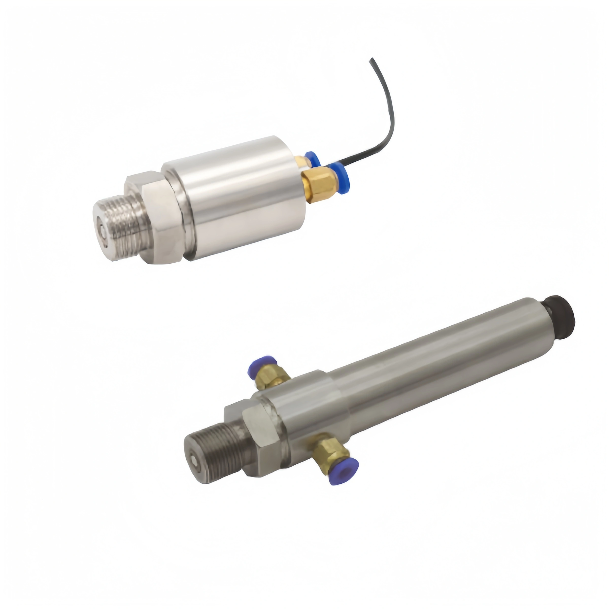
Water-Cooled Jacket Design: How the CYG409 Survives 450 °C Continuous
The piezoresistive silicon die at the heart of the CYG409 is the same family of sensing element used in the CYG402 high-temperature piezoresistive pressure sensor, where continuous operation is rated to 180 °C. The CYG409 lifts that ceiling to 450 °C by surrounding the sensing head with a coaxial water jacket that absorbs heat before it reaches the die.
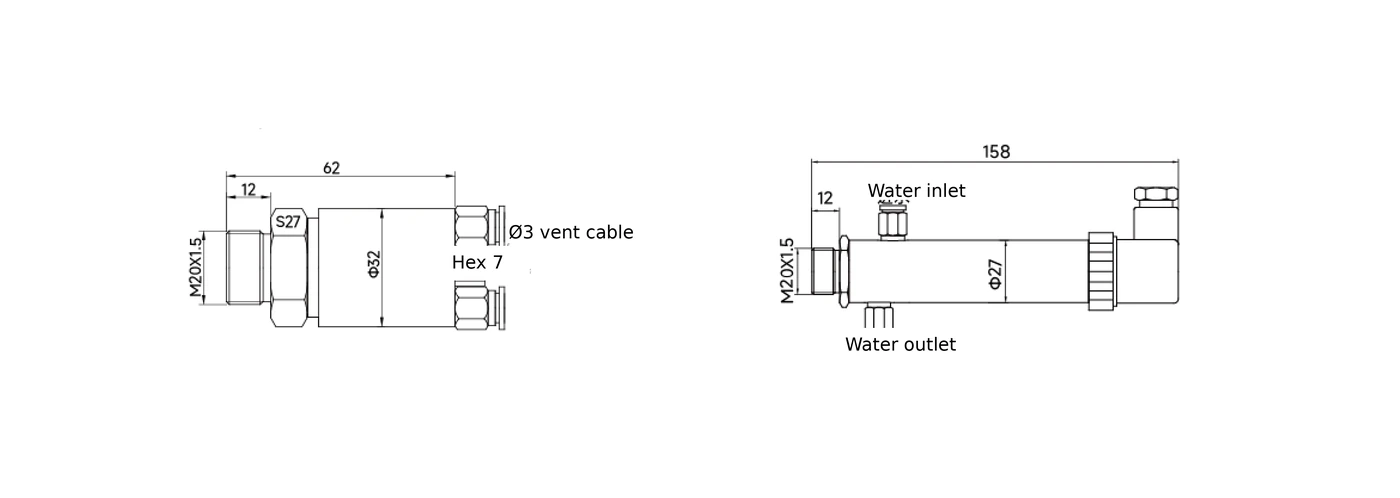
Cooling water enters one port on the M20 × 1.5 mounting body, circulates through the annular cavity around the sensing diaphragm, and exits a second port. The factory specification is 300 kPa to 700 kPa supply pressure at 2 L/min flow. Below 300 kPa the flow rate falls below the heat-removal threshold and the die temperature climbs into the 180 °C danger zone; above 700 kPa the seal life shortens. Two ports plumbed in series across multiple sensors is acceptable in a test stand provided that the last sensor in the loop still sees 300 kPa or more.
The same jacket also handles the dual-mode transient rating. For a 200 ms exposure the front face can see 2,000 °C, long enough for the deflagration front of a shock tube or detonation chamber to pass and be measured. For a longer 1,000 ms exposure the front face can see 1,000 °C, covering the post-burn relaxation period that follows the peak. After either pulse, the water jacket dissipates the absorbed heat and the sensor returns to the 450 °C continuous regime.
Application Scenarios: Where the CYG409 Earns Its Keep
The CYG409 is built for short, violent pressure events inside hot, sometimes incendiary, environments. Four application families drive most orders, split between the two range variants.
Solid-propellant closed-bomb testing uses the high-range CYG409 to characterise burn-rate curves at constant volume. The bomb wall reaches several hundred degrees during the burn, and pressure rises from atmospheric to tens of megapascals within milliseconds, then decays. The dual-mode transient rating covers both the peak flame front and the longer cool-down without breaking the water-cooled jacket regime.
Gun chamber internal ballistics for ordnance R&D mounts the high-range CYG409 in a flush-bore tap to record breech pressure during firing. Each shot lasts a few milliseconds at 50 to 100 MPa with chamber gas temperatures well over 1,000 °C. The 200-1,000 kHz natural frequency is high enough to resolve the propellant-ignition shock without ringing.
Shock-tube and detonation wavefront capture uses the low-range CYG409 to record the leading-edge step of a propagating shock or deflagration. Side-wall and end-wall taps both work with the M20 × 1.5 thread. Researchers studying gaseous detonation chemistry or supersonic flow physics use the low-range build because the wavefront pressure rise stays inside the 600 kPa ceiling.
Combustion-chamber pressure dynamics in jet-engine afterburners, rocket motor R&D, and pulsed-combustion boilers needs a sensor that survives continuous 450 °C wall contact while resolving the kHz-band combustion oscillations that drive flame instability. Either range model fits, depending on operating pressure.
Application-to-range selection matrix
| Application | Recommended range model | Why this choice |
|---|---|---|
| Solid-propellant closed-bomb burn-rate testing | High-range (1 MPa to 100 MPa) | Peak pressure typically 30 to 80 MPa |
| Gun chamber internal ballistics | High-range (1 MPa to 100 MPa) | Breech pressure 50 to 100 MPa, ms-scale duration |
| Shock-tube wavefront capture | Low-range (1 kPa to 600 kPa) | Leading-edge step stays below 600 kPa |
| Gaseous detonation research | Low-range or high-range | Range depends on initial fill pressure and Chapman-Jouguet state |
| Jet-engine afterburner combustion oscillation | High-range (1 MPa to 100 MPa) | Mean pressure 2 to 8 MPa with kHz oscillations |
| Pulsed-combustion boiler dynamics | Low-range (1 kPa to 600 kPa) | Working pressure typically below 500 kPa |
For outdoor blast wavefront work in open air, where mounting flush in a wall is not possible, see the CYG410 free-field pressure sensor in the same family.
How the CYG409 Compares: In-Family and Wider Market
The first comparison is inside the CYG400 family itself, because that is where most procurement decisions actually land: a buyer picks the CYG401 first, runs into a temperature wall, and escalates to the CYG409. The second comparison is technology-class, against the international charge-mode piezoelectric sensors that dominate the same niche.
In-family comparison (verified from LIVE product pages and the CYG409 PDF spec sheet)
| Item | CYG401 | CYG402 | CYG409 (this product) |
|---|---|---|---|
| Sensing technology | Piezoresistive | Piezoresistive | Piezoresistive |
| Pressure range | 4 MPa to 100 MPa | Negotiated | 1 kPa to 100 MPa (split) |
| Natural frequency | 200 kHz to 1,000 kHz | Negotiated | 200 kHz to 1,000 kHz |
| Continuous temperature | Standard | Up to 180 °C | Up to 450 °C |
| Transient temperature rating | Not rated | Not rated | 2,000 °C / 200 ms or 1,000 °C / 1,000 ms |
| Water cooling | None | None | Required (300-700 kPa, 2 L/min) |
| Typical use case | Closed cased dynamic measurement at ambient walls | Cased measurement on hot lines up to 180 °C | Combustion / ordnance / shock-tube with hot walls |
The CYG409 is the only variant in the family with an active cooling jacket and the only one with a transient temperature rating, which is what enables combustion-front and detonation work.
Wider-market positioning. Outside the CYG400 family, the comparable hardware is the charge-mode piezoelectric water-cooled high-temperature dynamic pressure sensor class supplied by international vendors such as Kistler and PCB Piezotronics. Charge-mode piezo gives higher temperature ceilings on a smaller diaphragm but requires a separate charge amplifier and high-impedance low-noise cabling, which raises installed system cost and complicates retrofits. The piezoresistive CYG409 keeps the readout chain simple: bridge output direct to a DAQ, or the matched CYG1409 module for a 4-20 mA loop. For test cells that already run on 4-20 mA plant cabling, the CYG409 plumbs in without an additional charge-amp bay.
Ordering Configuration: How to Specify a CYG409 on a PO
Five pieces of information lock in a CYG409 purchase order. Range model selects the low-range (1 kPa to 600 kPa) or high-range (1 MPa to 100 MPa) variant, and inside each model the buyer picks the specific full-scale value that brackets the expected peak with sensible headroom. Output chain chooses between the bare-sensor millivolt-bridge output (for buyers with their own bridge amp or DAQ) and the matched CYG1409 transmitter module that ships 4-20 mA or 0-5 V on a standard plant loop. Mounting is fixed at M20 × 1.5 external thread; confirm the test fixture has the matching internal thread and seal seat. Cable length and cooling-water fittings are the last two line items, both negotiated at order time based on the test cell layout.
Cooling Water Requirements and Installation Practice
The factory-specified cooling envelope is 300 kPa to 700 kPa supply pressure at 2 L/min flow. In practice three site conditions matter most. Water quality: use filtered or deionised water; particulates above roughly 50 µm risk eroding the annular cavity and gradually narrowing the cooling cross-section. Port orientation: mount inlet below outlet whenever possible so trapped air vents through the upper port and does not insulate the diaphragm during start-up. Freeze protection: in outdoor or unheated test cells, drain the jacket between sessions, or run a propylene-glycol mixture rated to the lowest expected ambient. After every long-duration high-temperature run, hold cooling flow for at least one full minute past shutdown to let the M20 × 1.5 body return to ambient before depressurising.
Frequently Asked Questions
Request a CYG409 Quote or Compare with the Non-Cooled CYG401
If your test cell needs continuous 450 °C wall contact, dual-mode transient survival up to 2,000 °C, and a 200-1,000 kHz dynamic response, the CYG409 is the right fit. Tell us the full-scale pressure, the expected peak temperature, and whether you want the bare sensor or the matched CYG1409 4-20 mA transmitter, and we will return a configured quotation.
If your line stays at room-temperature walls, the CYG401 high-frequency dynamic pressure sensor is the lower-cost alternative without the cooling jacket. For the full family overview see the CYG400 piezoresistive dynamic pressure family.