CYG1413 — Underwater Free-Field Pressure Transmitter
CYG1413 Underwater Free-Field Pressure Transmitter: Underwater Explosion Measurement
Sealed underwater transmitter for low-distortion shock-wave capture in underwater explosion (UNDEX) testing. 20 to 100 MPa range, 450–1000 kHz natural frequency, 0.2–0.3 µs rise time. Cavity-less flush diaphragm, waterproof housing and sealed cable, amplified 0–5 V output. Anti-IR optical option.
What an Underwater Free-Field Transmitter Is
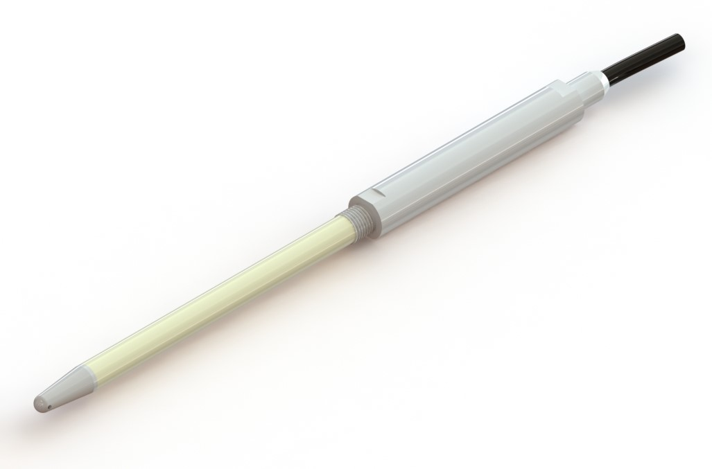
A free-field transmitter reads a pressure wave as it travels through the surrounding medium, with nothing nearby for it to bounce off. Suspended in open water on its cable, the CYG1413 lets the underwater shock wave wash over a flush diaphragm, so you read the incident pulse rather than a version reshaped by a tank wall, the bottom, or the free surface.
The CYG1413 is the underwater member of the CYG400 piezoresistive dynamic pressure family. It seals the cavity-less MEMS sensing element and its amplifier into a waterproof 195 × 132 mm housing with a sealed cable, so the unit survives immersion while keeping the diaphragm flush to the water. There is no trapped cavity to ring and smear the rising edge of the shock.
Four ranges, 20 to 100 MPa, cover underwater explosion work: charge tests in ponds and tanks, ship-shock trials, and underwater shaped-charge research. For free-field blast in air rather than water, use the CYG412 high-pressure free-field sensor, which shares these ranges in a teardrop probe form.
CYG1413 Technical Specifications
| Group | Parameter | Value |
|---|---|---|
| Sensing | Technology | MEMS piezoresistive silicon strain bridge |
| Diaphragm | Stainless steel, fully flush, cavity-less | |
| Anti-light interference | Anti-IR optical coating (option F4) | |
| Range & Speed | Range span | 20 / 40 / 60 / 100 MPa |
| Natural frequency | 450 / 600 / 800 / 1000 kHz (range-matched) | |
| Rise time | 0.3 µs (20–40 MPa); 0.2 µs (60–100 MPa) | |
| Accuracy | Transmitter accuracy | 0.5% / 1.0% FS (selectable) |
| Non-linearity | ±0.5% … ±1% FS | |
| Temperature drift | Zero 0.02–0.05 %FS/°C; sensitivity 0.02–0.05 %FS/°C | |
| Power & Output | Power | ±15 VDC |
| Output | Amplified 0–5 V | |
| Mechanical | Housing form | Sealed underwater housing 195 mm × 132 mm, with waterproof cable |
| Deployment | Cable-suspended; sealed gland, waterproof cable | |
| Wetted material | Water (silicon + stainless steel diaphragm) | |
| Environment | Operating temp | 0 to +50°C (in water) |
| Compensated temp | 0 to +50°C |
Range Selection: Four Ranges, One Underwater Housing
The CYG1413 ships in four ranges. The housing, cable, and rise time stay the same across all of them; only the sensing element changes with range. Pick the one whose full scale sits about 30 to 50% above your expected peak. That leaves headroom without throwing away bridge sensitivity.
| Range | Natural frequency | Rise time | Typical event |
|---|---|---|---|
| 0–20 MPa | 450 kHz | 0.3 µs | Near-field shock in water, small underwater charge |
| 0–40 MPa | 600 kHz | 0.3 µs | Close-in underwater detonation, ship-shock trials |
| 0–60 MPa | 800 kHz | 0.2 µs | Strong underwater reflected shock, hull loading |
| 0–100 MPa | 1000 kHz | 0.2 µs | Peak underwater explosion, mine and torpedo testing |
At 60 and 100 MPa the natural frequency climbs to 800 and 1000 kHz and the rise time tightens to 0.2 µs, so even the fastest underwater shock transients still register on the rising edge. For blast in air rather than water, the CYG412 free-field sensor shares these ranges in a teardrop probe form.
Where the CYG1413 Is Used
The 20–100 MPa band is built for one job: near-field, high-energy detonation. Peak pressure runs into the tens of MPa, and the rising edge lands somewhere between a few tenths of a microsecond and a microsecond.
Underwater Explosion (UNDEX)
Free-field shock-wave profiles from underwater charges in ponds, tanks, and open water, where the unit reads the incident pressure pulse before bottom or surface reflection arrives.
Ship-Shock & Naval Trials
Hull and onboard-equipment shock qualification against underwater detonation, where peak pressures reach tens of MPa with sub-microsecond rise.
Underwater Shaped-Charge
Close-in underwater shaped-charge and warhead characterization, where confined peak pressures reach 40–100 MPa over sub-microsecond rise times.
Mine & Torpedo Testing
Pressure-field mapping around underwater ordnance detonation for lethality, standoff, and protective-design studies.
Bubble-Pulse & Cavitation
Capturing the primary shock and the bubble-pulse train from an underwater explosion for energy-partition and cavitation analysis.
Subsea Structure Loading
Reflected and diffracted underwater blast loading on subsea structures, platforms, and protective barriers in the 20–100 MPa range.
Deployment: Underwater Placement and Sealing
An underwater transmitter only reads cleanly if you place, seal, and reference it right. Three rules cover most UNDEX test setups.
Face orientation. Point the diaphragm face toward the charge. The sealed housing takes the wavefront square on the diaphragm with the body trailing, which keeps diffraction and reflection off the face. Past about 15° off-axis, peak amplitude starts to read low by an angle-dependent amount.
Sealed deployment. Suspend the unit on its waterproof cable from a rigid frame, boom, or buoy at the test depth, and stop it swinging. Check the cable gland and housing seal before every immersion. Route the cable clear of the line between the unit and the charge so cable motion does not read back as noise.
Standoff and depth. Fix the radial standoff and the water depth precisely and log both with the shot. Underwater peak pressure falls off steeply with distance, so a 10% error in standoff turns into a 20-30% error in pressure. Take a hydrostatic zero at depth before the event so the dynamic record sits on a known baseline.
CYG1413 Ordering Code
Standard order format:
CYG1413 <range> <accuracy> <cable> <anti-IR> <custom>
| Segment | Code | Meaning |
|---|---|---|
| Range | 20 / 40 / 60 / 100 | Full-scale value in MPa |
| Accuracy | P4 / P5 | 0.5% / 1.0% FS |
| Cable | C1 / CS | Waterproof direct cable / double-shielded waterproof anti-interference cable |
| Anti-IR | F4 | Anti-IR optical coating (for line-of-sight to the detonation flash) |
| Custom | Q | Custom cable length, sealing depth, or housing configuration |
Worked example: CYG1413 60 P4 CS F4 Q — 0–60 MPa range, 0.5% accuracy, double-shielded waterproof cable, anti-IR optical coating, custom 25 m cable length per attached sheet.
CYG1413 FAQ
Technical Support
Three background guides for engineers specifying or commissioning a CYG1413 underwater transmitter. Open in a new tab; the deep-dives complement the spec-and-selection focus of this page.
Ready to Specify a CYG1413?
Send us the expected peak amplitude, the standoff distance and water depth, and the cable length you need. Our pressure-instrument engineers will reply with a CYG1413 range, ordering code, and lead time.
Our engineers usually reply within 12 business hours.