Orifice Plate Sizing Calculator
Size a concentric orifice plate to ISO 5167-2: solve the beta ratio and bore from your flow, pipe bore and target differential pressure, with the Reader–Harris/Gallagher discharge coefficient — then see the permanent pressure loss, its yearly energy cost, and the DP transmitter range to read it.
An orifice plate does not measure flow — it creates a differential pressure that a DP transmitter reads and turns into flow. For how to choose and apply that transmitter, see our guide to the differential pressure transmitter for flow measurement. Sizing the plate means choosing a bore, expressed as the beta ratio β = d/D, that produces a sensible differential at full flow: too large and the signal is weak, too small and you throw away pressure (and pumping energy) for the rest of the plant’s life. Because the ISO 5167-2 discharge coefficient depends on β and Reynolds number, the bore cannot be solved in one step — this tool iterates it for you, then reports the permanent loss, its annual cost, and the transmitter range that matches.
How orifice sizing works (and why it is iterative)
The ISO 5167-2 mass-flow equation ties everything together:
qm = (C / √(1 − β⁴)) · ε · (π/4) · d² · √(2 · ΔP · ρ₁)
Here qm is mass flow, C the discharge coefficient, ε the expansibility (1 for liquids), d the bore, β = d/D, ΔP the differential and ρ₁ the upstream density. Everything is known except the bore — but C is not a constant. The Reader–Harris/Gallagher equation that ISO 5167-2 adopts makes C a function of β, the pipe Reynolds number ReD and the tapping arrangement, so you cannot rearrange the equation for d directly. The calculator fixes ReD from your flow (ReD = 4qm/πμD, independent of bore), then converges β by bisection until the equation balances. With the default case — 30 m³/h of water in a 100 mm line at a 25 kPa target — it lands on β ≈ 0.490, a 49.0 mm bore, C ≈ 0.606 at ReD ≈ 1.1×10⁵.
Choosing beta: the signal-versus-energy trade-off
For a fixed flow and pipe, the only way to raise the differential is to shrink the bore — and a smaller bore permanently destroys more pressure. The permanent (non-recoverable) loss across a square-edged orifice is a large fraction of the differential it creates, and that fraction grows as β falls. ISO 5167-2 gives it as Δω/ΔP = (√(1 − β⁴(1 − C²)) − Cβ²) / (√(1 − β⁴(1 − C²)) + Cβ²). The practical cost is the headline this calculator surfaces. Take the same 30 m³/h of water in DN100 and ask for a bigger differential:
| Target ΔP | Beta β | Bore | Permanent loss | Pumping cost/yr* |
|---|---|---|---|---|
| 10 kPa | 0.602 | 60.2 mm | 6.3 kPa (62%) | ~$65 |
| 25 kPa | 0.490 | 49.0 mm | 18.5 kPa (74%) | ~$193 |
| 50 kPa | 0.416 | 41.6 mm | 40.5 kPa (81%) | ~$422 |
| 100 kPa | 0.352 | 35.2 mm | 86.1 kPa (86%) | ~$898 |
*At $0.10/kWh, 70% pump efficiency, 8760 h/yr. Asking for four times the differential here multiplies the lifetime pumping bill roughly fourteen-fold, from about $65 to $898 a year, with no measurement benefit once the signal is already comfortable. That is why a beta around 0.45–0.60 with a modest differential is usually the economical choice, and why “just use a high DP so the signal is strong” is an expensive habit on large or continuously running lines. The calculator prices your own case so the trade-off is in dollars, not abstractions.
From orifice ΔP to the DP transmitter range
The plate’s full-scale differential is the transmitter span. Set the transmitter’s upper range value (URV) to that differential and its lower range value to zero, and pick a cell whose maximum span comfortably covers it — but do not over-reach. A transmitter run at a large turndown (calibrated span far below its maximum span) carries proportionally more error, and the square-root flow relationship then amplifies that error near zero flow. As a rule, keep the turndown modest (single digits) for accurate low-flow indication; if your full-scale differential is small, choose a low-range cell rather than turning down a high-range one. The calculator reports the differential to set and flags when the implied turndown is getting aggressive. HMK DP transmitters that read orifice signals directly — the HM3051, HM31 and HM1151 — appear below, with ranges from a few kilopascals upward.
Straight-run requirements you cannot ignore
ISO 5167-2 only holds if the velocity profile reaching the plate is fully developed, which means minimum straight lengths of bare pipe upstream and downstream of the orifice. Those lengths are counted in pipe diameters D and — importantly — they grow steeply as β rises, so a high-β plate that looks attractive for low pressure loss can demand far more straight run than the pipe layout allows. Representative upstream minimums for a single 90° bend (ISO 5167-2 Table 3, zero additional uncertainty) illustrate the trend:
| Beta β | Upstream of orifice (single 90° bend) | Downstream |
|---|---|---|
| 0.20 | 10 D | 4 D |
| 0.40 | 14 D | 5 D |
| 0.50 | 22 D | 6 D |
| 0.60 | 42 D | 7 D |
| 0.67 | 44 D | 7 D |
The jump from 22 D at β = 0.5 to 42 D at β = 0.6 is the rule, not a typo: high-β plates are profile-sensitive. Where the run is short, either drop to a lower β (and accept the pressure loss), fit a flow conditioner, or switch to a primary element that tolerates less straight pipe. Always confirm the exact figure against ISO 5167-2 Table 3 for your specific upstream fitting — two bends in perpendicular planes, a reducer or a valve each have their own column.
Validity limits — when ISO 5167-2 stops applying
The standard is only valid inside a defined envelope, and pushing past it silently is a classic sizing error. For square-edged orifice plates ISO 5167-2 requires β between 0.10 and 0.75, a bore d of at least 12.5 mm, pipe diameter D from 50 mm to 1000 mm, and a Reynolds number above a β-dependent floor (ReD ≥ 5000 for β ≤ 0.56, and ReD ≥ 16000β² above that). If your inputs drive the solution outside any of these, the calculator says so rather than returning a confident but invalid bore. The usual fixes are to relax the target differential (a too-high ΔP forces β below 0.10), enlarge or reduce the line, or for very low Reynolds numbers move to a different primary element.
Gas and vapour: the expansibility factor
For compressible flow the fluid expands as it accelerates through the bore, so ISO 5167-2 multiplies the equation by an expansibility factor ε below 1: ε = 1 − (0.351 + 0.256β⁴ + 0.93β⁸)(1 − (p₂/p₁)1/κ), with p₂/p₁ set by the differential and κ the isentropic exponent. Switch the fluid type to gas and enter the upstream absolute pressure and κ; the tool applies ε in the iteration. For liquids ε is exactly 1 and the term disappears. Note that ISO 5167-2 limits the orifice differential to no more than about a quarter of the upstream absolute pressure for compressible flow — beyond that the simple expansibility model is out of range.
Frequently Asked Questions
What beta ratio should I use for an orifice plate?
For most liquid services a beta between about 0.45 and 0.60 balances a usable differential against permanent pressure loss and straight-run demand. Lower beta gives a stronger signal but wastes more pressure; higher beta saves energy but needs much more straight pipe and becomes profile-sensitive. ISO 5167-2 allows 0.10 to 0.75.
How do I size an orifice plate from flow and pressure drop?
Fix the flow, pipe bore, fluid density and viscosity, and a target differential, then solve the ISO 5167-2 equation for the bore. Because the discharge coefficient depends on beta and Reynolds number, the bore must be found iteratively — this calculator does that and returns beta, bore, the discharge coefficient and the permanent pressure loss.
Does an orifice plate’s pressure loss go away downstream?
No. Part of the differential is recovered as the flow re-expands, but a large fraction — 60% to 85% for typical beta values — is permanently lost and must be made up by the pump or fan for the life of the installation. That permanent loss, not the measured differential, is the real energy cost of an orifice meter.
Recommended DP Transmitters
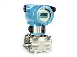 HM3051Smart DP, HARTCapacitive cell, ±0.1% FS, HART re-ranging — the high-turndown choice for orifice flow.
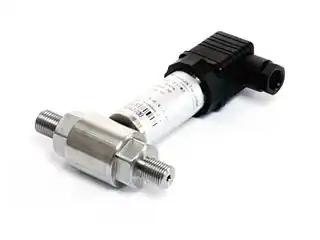 HM31Silicon DP, 4-20mA/HART0–10 kPa to 2 MPa DP, 20 MPa static, ±0.1% FS — flow and level.
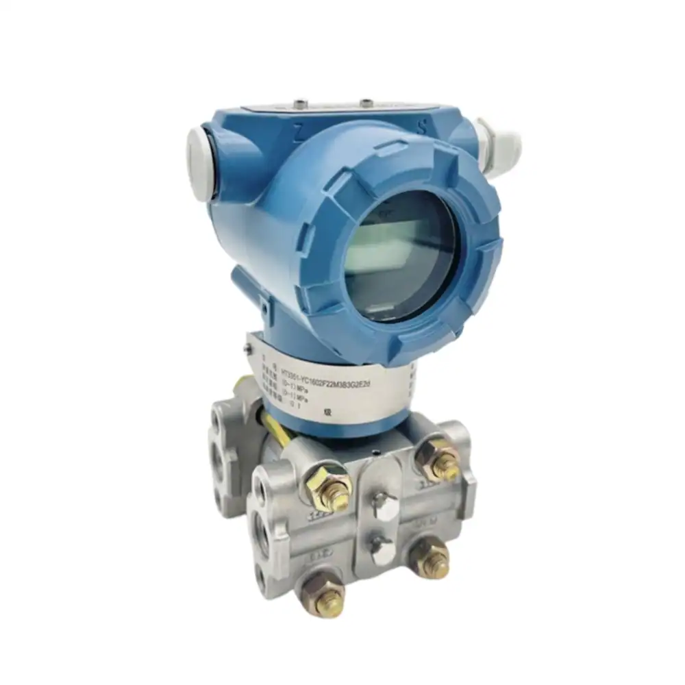 HM1151Capacitive DPClassic 1151 form, ±0.25% FS, 500%/600% overload — rugged DP workhorse.
Related Tools
Sizing an orifice run and need the transmitter to match?
Send us the flow, line size, fluid and the differential this tool returns, and we will confirm the DP transmitter range and model for the job.