Ex i Entity Parameter Validator
Validate an intrinsically safe (Ex i) loop in seconds. Enter transmitter, barrier, and cable parameters; the tool checks all five IEC 60079-11 inequalities and flags any that fail, with an optional 30% NEPSI commissioning margin.
Transmitter side (from datasheet)
Barrier / galvanic isolator (safe-area side)
Field cable (loop run)
Try a preset
Common Ex i Pairings: Quick Reference Table
| Pairing | Uo / Io / Po | Co / Lo | Tx Ci / Li | Cable headroom |
|---|---|---|---|---|
| HMK HM60 + Pepperl-Fuchs KFD2-STR Zener barrier | 25.2 V / 93 mA / 587 mW | 107 nF / 3300 μH | 20 nF / 100 μH | 435 m at 200 pF/m (with 30% margin: 312 m) |
| HMK HM50 + Phoenix Contact MACX MCR-EX-SL galvanic isolator | 24 V / 100 mA / 600 mW | 160 nF / 5000 μH | 15 nF / 50 μH | 906 m at 160 pF/m (with 30% margin: 689 m) |
| HMK HM28 + STAHL 9165 isolator | 25.2 V / 93 mA / 600 mW | 107 nF / 3300 μH | 5 nF / 10 μH | 510 m at 200 pF/m (with 30% margin: 379 m) |
| HMK HE60 OEM + KFD2-STR Zener barrier | 25.2 V / 93 mA / 587 mW | 107 nF / 3300 μH | 8 nF / 25 μH | 495 m at 200 pF/m (with 30% margin: 366 m) |
How to Use This Validator
- Read the transmitter datasheet for the five Ex i entity parameters under “Intrinsic Safety Marking”: Ui, Ii, Pi, Ci, Li. These are the device’s safety ceilings.
- Read the barrier or galvanic isolator datasheet for Uo, Io, Po, Co, Lo on the field-side terminal pair. Use the entity-parameter table for the specific output channel you are wiring.
- Look up the cable spec. Typical instrumentation cable runs 150 to 250 pF per metre for capacitance and 0.7 to 1.2 μH per metre for inductance. Use the actual cable run length in metres, end-to-end.
- Click Validate Loop. The tool reports five PASS / FAIL checks. All five must pass for the loop to qualify as Ex i certified in that configuration.
- Apply the 30% NEPSI margin for cable runs over 200 m, outdoor installations exposed to seasonal temperature swings, or any commissioning that will be filed with NEPSI / EAC / IECEx audit teams. Toggle the margin off only for the bare IEC 60079-11 baseline check.
The Five Entity-Parameter Inequalities
An Ex i loop is certified only when all five inequalities below hold simultaneously, with the barrier at the safe-area side and the transmitter at the field side:
- 1. Uo ≤ Ui — barrier output voltage cannot exceed transmitter input rating
- 2. Io ≤ Ii — barrier output current cannot exceed transmitter input current rating
- 3. Po ≤ Pi — barrier output power cannot exceed transmitter input power rating
- 4. Co ≥ Ci + (Ccab/m × Length) — barrier max external capacitance must absorb device + cable storage
- 5. Lo ≥ Li + (Lcab/m × Length) — barrier max external inductance must absorb device + cable storage
The first three inequalities cap the total energy that can reach the field side under fault. The last two ensure the energy stored in cable + device reactive elements cannot, during a discharge transient, exceed the gas-group ignition threshold for the rated zone.
The optional 30% NEPSI commissioning margin raises inequalities 4 and 5 to 1.3 × (Ci + Ccable) and 1.3 × (Li + Lcable). This is standard practice in commissioning reports filed to NEPSI in China and increasingly referenced by Indian and Vietnamese audit teams reviewing imported instrumentation, because cable capacitance can drift up to 10% across an Asian summer temperature swing.
More HMK engineering tools to use alongside this validator:
- Pressure Unit Converter — bar / PSI / kPa / atm / kg/cm² conversion for spec sheets and field calibration
- Intrinsically Safe Pressure Transmitter: Ex i Selection & Spec Guide — explainer companion article covering ATEX, IECEx, GB 3836 certification
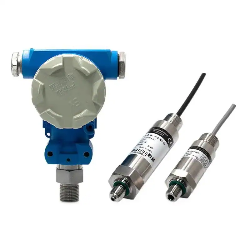
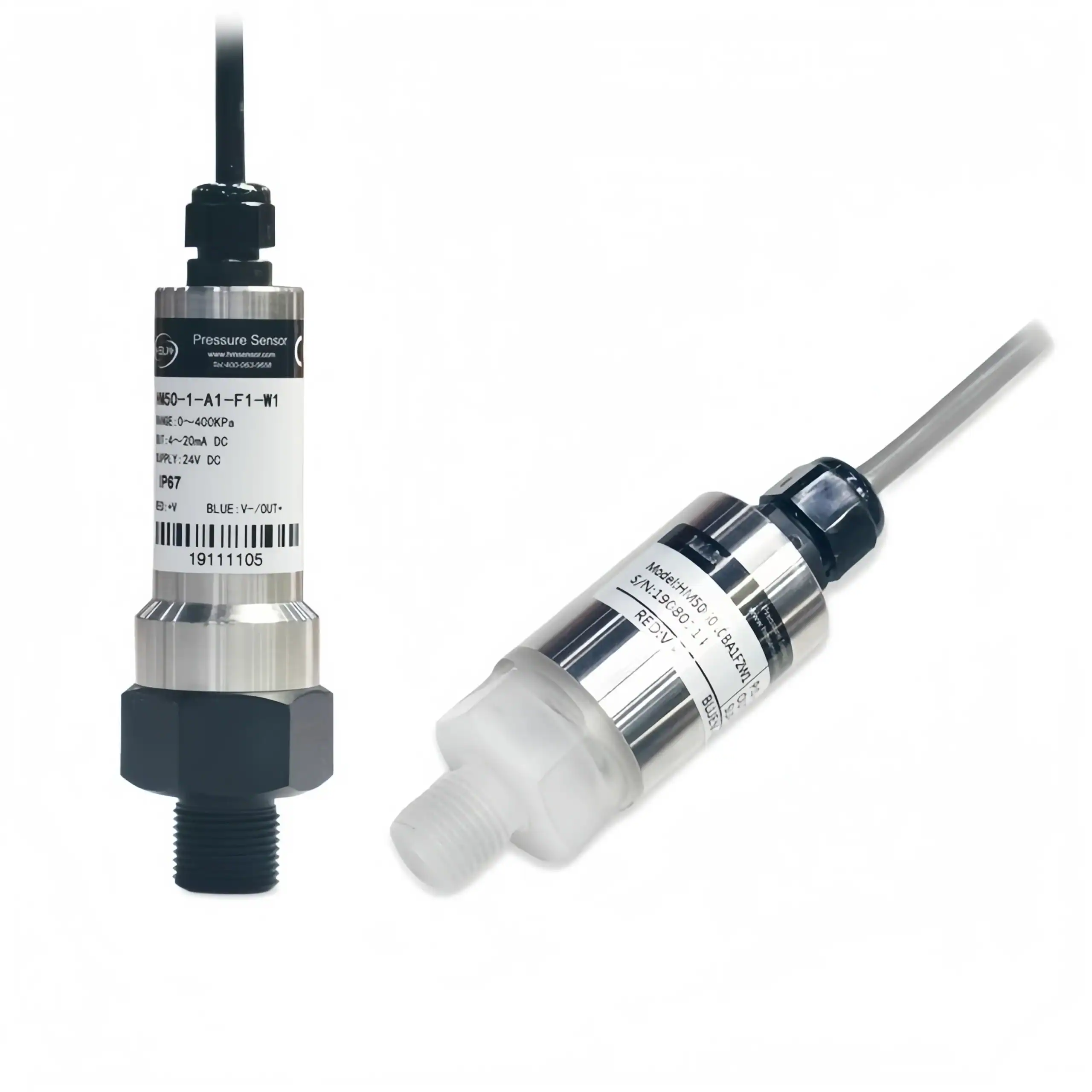
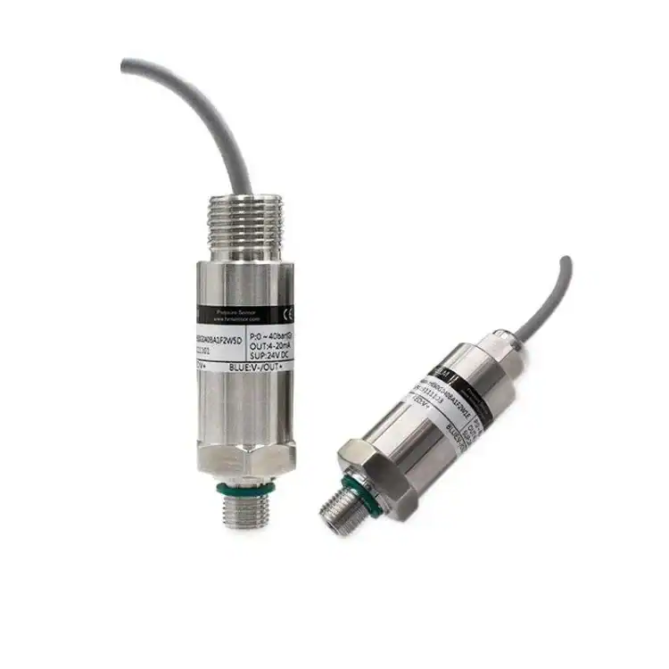
Recommended Ex i Pressure Products
Frequently Asked Questions
Need to Spec an Ex i Pressure Loop for Your Plant?
If your validator output flags any inequality as failed and you are not sure which side to change — barrier, cable, or transmitter — send the spec to the HMK pressure engineering team. We work through the entity-parameter math with you and recommend a configuration that passes both IEC 60079-11 and NEPSI commissioning checks.
Our engineers typically respond within 12 business hours with a complete entity-parameter analysis and product recommendation.