HM SERIES — DIFFERENTIAL PRESSURE TECHNOLOGY
HM31 Differential Pressure Transmitter
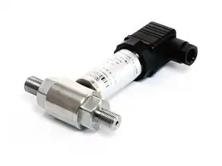
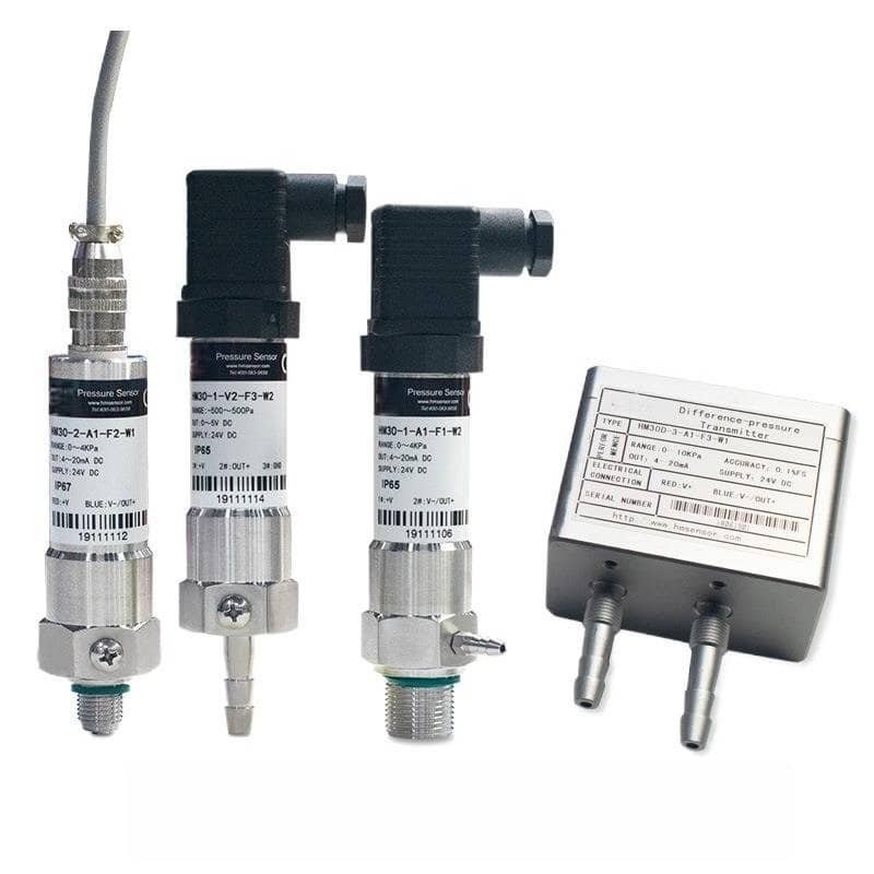
High-accuracy differential pressure transmitter featuring piezoresistive sensing technology. Covers DP ranges from 10 kPa to 2 MPa with up to ±0.1% FS accuracy, withstanding static pressures up to 20 MPa. All stainless steel construction for industrial process control, flow measurement, and aerodynamic testing.
Product Overview
The HM31 Differential Pressure Transmitter is a compact, high-performance instrument designed for precise measurement of differential pressure in industrial processes. With configurable ranges from 10 kPa to 2 MPa and accuracy options up to ±0.1% FS, it delivers reliable measurement data for flow monitoring, filter condition assessment, and process pressure drop applications.
Built around an advanced piezoresistive differential pressure sensing element paired with a dedicated signal conditioning ASIC, the HM31 achieves exceptional thermal stability with zero and span temperature coefficients of just ±0.02% FS/°C (typical). The all-stainless-steel wetted construction provides broad chemical compatibility for both liquid and gas media, while the compact housing keeps installation weight under 250 grams.
A standout feature of the HM31 is its exceptional static pressure resistance — up to 20 MPa on both the high and low ports — making it particularly well-suited for flow measurement in high-pressure pipelines where large line pressures coexist with small differential pressures. The optional Ex ia II CT5 intrinsic safety certification further extends its application into hazardous Zone 0/1 environments in petrochemical and mining operations.
Multiple output options (4-20mA, 0-5V, 1-5V, 0.5-4.5V) and process connections (M20×1.5, G1/4) ensure seamless integration with existing control infrastructure. With a ≤2 ms response time and 10⁸ pressure cycle life rating, the HM31 is engineered for demanding, long-service industrial environments.
Technical Specifications
| Parameter | Specification |
|---|---|
| Measuring Range | 0~10 kPa … 2 MPa (differential) |
| Pressure Type | Differential |
| Overall Accuracy | ±0.1% FS / ±0.25% FS / ±0.4% FS (selectable) |
| Long-Term Stability | ±0.3% FS/year (≤200 kPa) / ±0.1% FS/year (≥200 kPa) |
| Zero Temperature Error | ±0.02% FS/°C (typical) / ±0.05% FS/°C (max) |
| Sensitivity Temperature Error | ±0.02% FS/°C (typical) / ±0.05% FS/°C (max) |
| Static Pressure Effect | ±0.05% FS / 100 kPa |
| Max Static Pressure | ≤20 MPa |
| Output Signal | 4-20mA (2-wire) / 0-5V / 1-5V / 0.5-4.5V (3-wire) |
| Power Supply | 12~36 VDC (typically 24 VDC) |
| Operating Temperature | -10 ~ 80°C |
| Compensated Temperature | -10 ~ 50°C |
| Response Time | ≤2 ms |
| Insulation Resistance | 100 MΩ @ 500 VDC |
| Vibration Resistance | ≤1% change after 3g RMS, 30-2000 Hz |
| Shock Resistance | ≤1% change after 100g, 10 ms |
| Life Cycle | 1 × 10⁸ pressure cycles |
| Wetted Materials | Stainless steel (body & diaphragm) |
| Medium | Liquids or gases compatible with wetted materials |
| Process Connection | M20×1.5 / G1/4 / Custom |
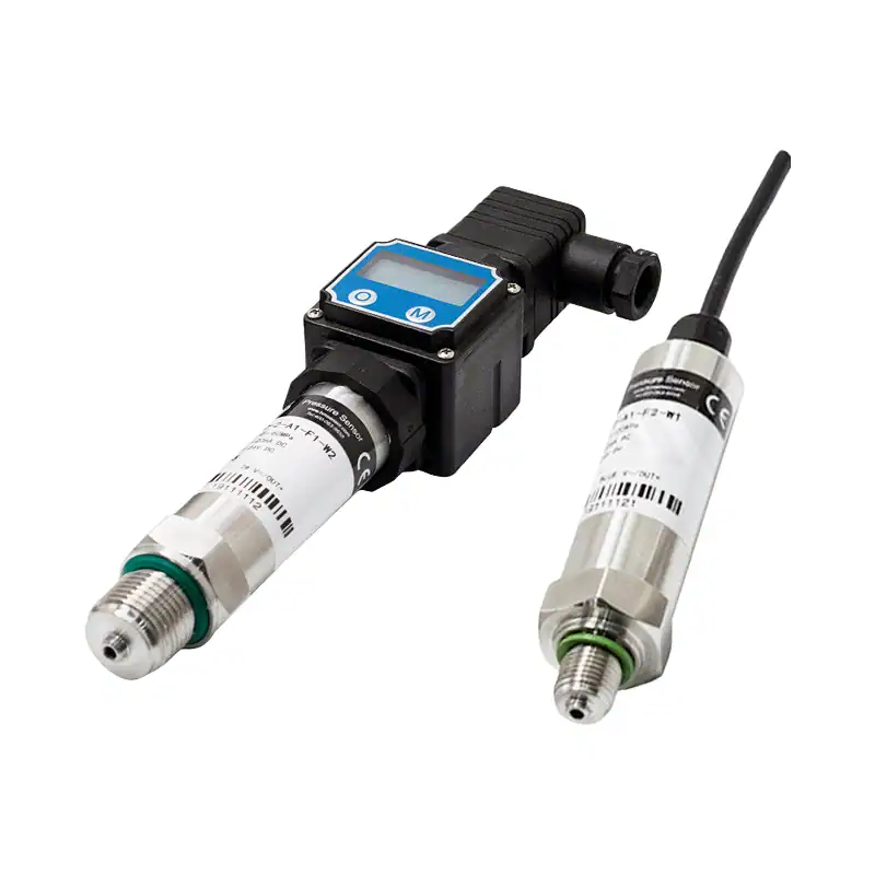
| Electrical Connection | DIN 43650A (IP65) / Cable gland (IP67, 2m) |
| Protection Grade | IP65 (connector type) / IP67 (cable type) |
| Explosion Proof | Ex ia II CT5 (optional) |
| Weight | Approx. 250 g |
| Certifications | CE |
Note: Custom ranges, output signals, and process connections are available upon request. Contact our engineering team for application-specific configurations.
Overload Pressure Limits by Range
| DP Range | Positive Overload | Negative Overload |
|---|---|---|
| 10 ~ 50 kPa | 250 kPa | 100 kPa |
| 50 ~ 100 kPa | 300 kPa | 200 kPa |
| 0.1 ~ 0.2 MPa | 0.4 MPa | 0.3 MPa |
| 0.2 ~ 0.5 MPa | 1.0 MPa | 0.5 MPa |
| 0.5 ~ 1 MPa | 2 MPa | 0.7 MPa |
| 1 ~ 2 MPa | 4 MPa | 1 MPa |
Key Features
High-Accuracy Differential Measurement
±0.1% FS accuracy with ±0.02% FS/°C thermal stability ensures precise differential pressure readings across the full -10 to 80°C operating temperature range.
Extreme Static Pressure Resistance
Withstands up to 20 MPa static pressure while measuring differential pressures as low as 10 kPa — ideal for high-pressure pipeline flow measurement applications.
All Stainless Steel Construction
Full stainless steel wetted parts and compact housing (250g) provide excellent corrosion resistance with easy installation in tight spaces and harsh environments.
Wide Differential Range Coverage
Configurable from 10 kPa to 2 MPa differential pressure, covering micro-differential, standard flow, and high-differential applications with a single product family.
Multiple Output Options
Supports 4-20mA two-wire, 0-5V, 1-5V, and 0.5-4.5V three-wire outputs, compatible with virtually any PLC, DCS, or data acquisition system.
Intrinsically Safe Option
Optional Ex ia II CT5 certification enables safe deployment in hazardous Zone 0/1 environments including petrochemical, mining, and gas processing facilities.
Applications
Industrial Process Control
Monitor differential pressure across filters, heat exchangers, and process vessels. The ±0.1% FS accuracy and 20 MPa static pressure rating ensure reliable readings in high-pressure systems.
Flow Measurement
Calculate volumetric or mass flow rates using orifice plates, Venturi tubes, or flow nozzles. The 2 ms response time and wide DP range (10 kPa–2 MPa) provide real-time flow data.
HVAC & Clean Room Monitoring
Measure differential pressures from 10 kPa for building pressure control, duct airflow monitoring, and cleanroom positive/negative pressure verification.
Medical & Laboratory Equipment
Precision differential pressure sensing for ventilator airflow monitoring, filter integrity testing, and laboratory gas flow control applications requiring ≤2 ms response.
Hydraulic & Pneumatic Systems
Monitor pressure drops across hydraulic filters and pneumatic regulators. IP67 protection and vibration resistance (3g RMS) ensure reliability in industrial machinery environments.
Oil & Gas Processing
Intrinsically safe Ex ia II CT5 option enables deployment in hazardous areas for wellhead monitoring, separator level detection, and pipeline flow metering applications.
Ordering Guide
Use the model code structure below to specify your HM31 configuration. Example: HM31 (0~50KPa) — 1 — A1 — F2 — W1 orders a ±0.4% FS accuracy unit with 4-20mA output, G1/4 connection, and cable output (IP67).
| Selection Code | Options |
|---|---|
| Model | HM31 (specify DP range, e.g., 0~50 kPa or 0~2 MPa) |
| Accuracy — 1 | ±0.4% FS |
| Accuracy — 2 | ±0.25% FS |
| Accuracy — 3 | ±0.1% FS |
| Output — A1 | 4-20mA (2-wire) |
| Output — V1 | 1-5V DC (3-wire) |
| Output — V2 | 0-5V DC (3-wire) |
| Output — V3 | 0.5-4.5V DC (3-wire) |
| Connection — F1 | M20×1.5 external thread |
| Connection — F2 | G1/4 internal thread |
| Connection — F0 | Special (specify in order) |
| Cable — W1 | Cable type (IP67, 2m standard) |
| Cable — W2 | DIN 43650A connector (IP65) |
| Option — E | Intrinsically safe Ex ia II CT5 |
Related Products
Frequently Asked Questions
Need a Differential Pressure Measurement Solution?
Tell us about your differential pressure measurement requirements — including media type, DP range, static pressure, and output signal. Our engineering team will recommend the optimal HM31 configuration for your specific application.
Our engineers typically respond within 12 business hours with detailed technical specifications and pricing.